LOPA and SIL in the process industry
≈ 21 min read · 4,299 words
On an icy road four things protect you: good tyres, ABS, the seat belt and the airbag. If any one of them is missing, the others may still catch you, only the protection gets thinner. In a chemical plant the same question comes up, with far higher stakes: how many genuinely independent things stand between the failure and the explosion?
LOPA counts how many independent protection layers stand between the hazard and the accident; SIL sets how reliable the missing layer must be.
LOPA (Layers of Protection Analysis) is a semi-quantitative risk analysis: it multiplies the frequency of the initiating event by the probability of failure on demand (PFD) of the layers, and measures the result against the tolerable event frequency. SIL (safety integrity level) is the continuation: it says what reliability the safety instrumented function (SIF) must have to cover the residual risk.
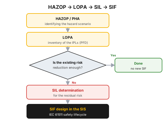 Figure 1 — the decision chain leading from HAZOP to the SIF.
Who is this for?
Section titled “Who is this for?”This article is for those who live with the protection layers, or decide about them: plant manager · process engineer · process control and instrumentation engineer · HSE / process safety specialist · reliability engineer · shift supervisor.
Learning objectives
Section titled “Learning objectives”After reading this article you will be able to:
- explain what LOPA is and what SIL is, and which of them answers what;
- decide about a layer whether it can be credited as an IPL, on the basis of the four standard requirements;
- carry out a LOPA multiplication from an initiating-event frequency and PFD values;
- say when operator action cannot be credited, and why the process safety time decides it;
- read the required PFD and RRF out of a SIL table, and recognize when you have to switch to a quantitative method.
The essence
Section titled “The essence”- LOPA: we multiply the frequency of the initiating event by the PFD of the independent protection layers (IPL), and compare it with the tolerable frequency. If the product is too large, risk reduction is missing.
- IPL is only a layer that meets the four requirements of the standard: independent, specific, dependable (quantifiable PFD/RRF) and auditable.
- SIL: the reliability requirement, in PFD and RRF, of the SIF that fills the gap (IEC 61508 / 61511). It is not a property of equipment but a property of the function: it applies to the whole loop.
- Empirical limit: an alarm plus operator action is worth at most an RRF 10 credit, and only with an intervention time of at least 10 minutes.
- The value of the credited layers depends on their actual availability: a layer that is bypassed, has an overdue test or shares a sensor exists on paper only.
Why it matters (the stakes)
Section titled “Why it matters (the stakes)”The hazard of a plant does not become bearable because “there are safety systems,” but because how much risk reduction they give is countable. LOPA is what makes this a number, and this is why the uncomfortable question falls out of it: how many layers did we believe to be independent when in fact they all hang on a single transmitter?
The stakes are high because layers disappear quietly. An isolation takes the interlock out of service, because of a missed trip test nobody knows whether the valve still opens, and an alarm limit shifted without an MOC invalidates the analysis. This is how five layers of protection on paper become two.
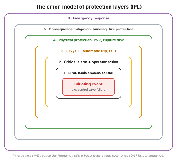 Figure 2 — the onion model of the protection layers: every layer is one more chance to stop the accident.
What is LOPA and what is SIL?
Section titled “What is LOPA and what is SIL?”Both are risk analysis methods that fit into the toolbox of process hazard analysis (PHA) alongside HAZID, HAZOP, FMEA, FTA and ETA. The order is not accidental: HAZOP uncovers the hazard scenarios, and LOPA quantifies for these whether the risk reduction is sufficient.
- LOPA: an extension of event tree analysis (ETA) that takes stock of the initiating event and the layers of protection so that the initiating event cannot turn into an accident. The layers are mostly devices, but operator action can also be a layer if there is enough time available to react.
- SIL: a semi-quantitative method for deciding whether a SIF is needed as a layer of protection, and if so, what probability of failure on demand (PFD) it must guarantee. SIL determination is part of the analyze phase of the safety life cycle.
SIL analysis began in the United States in the mechanical industry. In 1996 the ANSI/ISA-84.01 standard was published, and in Europe its counterpart, IEC 61508, which IEC 61511 tailors to the process industry. In a Seveso-classified plant all this is the technical backbone of preventing major accidents.
How does LOPA decide whether a SIF is needed?
Section titled “How does LOPA decide whether a SIF is needed?”With a single multiplication. If the frequency of the initiating event and the PFD of the layers, as a product, stay below the tolerable limit, there is nothing to do; if they are above it, a layer is missing, and this has to be filled with a SIF. The details live in the elements of the multiplication.
1) Quantifying the chain of layers
Section titled “1) Quantifying the chain of layers”Every layer gives a reduction of one or more orders of magnitude: a PFD of 0.1 means a tenfold (RRF 10), a PFD of 0.01 a hundredfold (RRF 100) risk reduction.
A textbook example is the explosive atmosphere of a furnace: three layers protect it, the BPCS/SDCD control, a SIF and the operator action:
- formation of an explosive atmosphere: f = 1 × 10⁻¹/yr
- BPCS/SDCD failure: PFD = 1 × 10⁻¹
- SIF failure: PFD = 1 × 10⁻²
- failure of the operator action: PFD = 1 × 10⁻¹
f(furnace explosion) = 10⁻¹ × 10⁻¹ × 10⁻² × 10⁻¹ = 1 × 10⁻⁵/yr
We measure this against the bands of the risk matrix: above 0.1/yr high, 0.1–0.01 moderate, 0.01–0.001 low, 0.001–0.0001 very low, below 0.0001/yr negligible. So 1 × 10⁻⁵/yr falls into the negligible band.
The frequency of the initiating event is not to be guessed: projects fix a rule set. Typical values:
| Initiating event | Frequency (1/yr) |
|---|---|
| BPCS/DCS loop failure (transmitter, controller, valve) | 0.1 |
| Regulator failure | 0.1 |
| Spurious closing or opening of a shutdown valve | 0.04 |
| Spurious full opening of a safety valve | 0.01 |
| Heat exchanger tube leak | 0.01 |
| Leak of a single pump seal | 0.1 |
| Centrifugal pump trip | 0.4 |
| General operator error | 0.1 |
| Loss of cooling water | 0.1 |
LOPA can be static (calculating with a constant PFD) or time-dependent; the latter takes into account that the reliability of a layer degrades between tests, so the test interval can also be rationalized.
2) What counts as an IPL?
Section titled “2) What counts as an IPL?”A protection layer gets credit if it meets, at the same time, the four requirements of Annex F9 of IEC 61511-3:
- Independence: it must be independent of the initiating cause and of the other layers; any failure of one layer must not cause the failure of another layer.
- Specificity: it must detect and prevent the given hazardous event, or reduce its consequence.
- Dependability: its risk-reducing capability must be known and quantifiable (RRF or PFD). Without this there is nothing to multiply by, so there is no credit either.
- Auditability: it must be testable, validatable, maintainable.
Two mnemonics help operational judgement. The layer should be effective (the “3 Enough’s”: Big, Fast, Strong Enough), and it should be identifiable (the “3 D’s”): it should Detect the initiating event, Decide about the intervention, and Deflect the unwanted consequence.
A usual IPL classification and the risk reduction factors assigned to it:
| Independent protection layer (IPL) | RRF | SIL equivalence |
|---|---|---|
| Safety (pressure relief) valve, rupture disk | 100 | mechanical |
| SIF, two-out-of-three (2oo3) voting, in an independent fail-safe PLC | 100 | SIL 2 |
| SIF, one-out-of-one (1oo1), in an independent fail-safe PLC | 10 | SIL 1 |
| Independent BPCS/DCS instrumentation (separate from the initiating cause) | 5 | – |
| Critical alarm plus intervention carried out in time | max. 10 | – |
| Single check valve | 5 | – |
| Dual, diverse check valves | 50 | – |
| Dike (bund), fireproofing | 100 | consequence-reducing |
3) Operator action as a layer
Section titled “3) Operator action as a layer”Operator action is an IPL if and only if the alarm signals in time and the operator has enough time to diagnose and to act. This is measured by the process safety time (PST): the interval between the start of the event and the occurrence of the hazardous event.
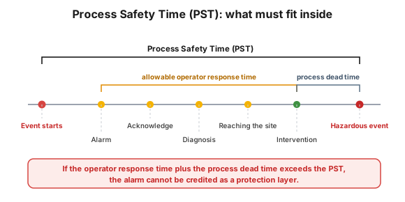 Figure 3 — the whole operator response time and the dead time of the process must both fit inside the PST.
The conditions are strict. The available intervention time must not be less than 10 minutes, the operator must be documented as trained, and a written alarm response procedure must be available. Rule of thumb: one operator = one safety intervention / 10 minutes. The creditable reaction time in the project rule sets is typically 2 minutes for a critical alarm and 10 minutes for other alarms. The PFD is a function of time and stress (operator of average competence, event recognized):
| Available intervention time | Circumstance | PFD |
|---|---|---|
| 10 min < t < 40 min | under stress | 1 – 0.5 |
| 10 min < t < 40 min | stress-free | 0.5 – 0.1 |
| 40 min < t < 24 h | stress-free | 0.1 – 0.05 |
| t > 24 h | stress-free | 0.05 – 0.01 |
The RRF taken into account for the alarm system and the operator action belonging to it must not be more than 10 (the PFD must not be smaller than 0.1), not even with a rationalized alarm. If the scenario demands more, the system has to be designed in accordance with IEC 61508/61511, or a separate SIF has to be built into the SIS.
Two constraints: a credited alarm must not share its sensor with the control system or with the SIS (in the case of a common part only one protection layer may be taken into account), and it is not recommended to assign IPL credit to more than one safety-critical alarm for a single demand scenario.
4) SIL: the reliability requirement of the missing layer
Section titled “4) SIL: the reliability requirement of the missing layer”If LOPA signals a gap, SIL determination says what integrity the SIF must have. Every SIF has a SIL number, and the SIL applies to the whole loop (sensor, logic solver, final element), not to a single component. Its definition is the PFD, or its reciprocal, the RRF:
| SIL | PFD (demand mode) | Availability | RRF = 1/PFD |
|---|---|---|---|
| SILa | 10⁻¹ ≤ PFD < 1 | – | 1 – 10 |
| SIL 1 | 10⁻² ≤ PFD < 10⁻¹ | > 90 – 99% | 10 – 100 |
| SIL 2 | 10⁻³ ≤ PFD < 10⁻² | > 99 – 99.9% | 100 – 1,000 |
| SIL 3 | 10⁻⁴ ≤ PFD < 10⁻³ | > 99.9 – 99.99% | 1,000 – 10,000 |
| SIL 4 | 10⁻⁵ ≤ PFD < 10⁻⁴ | > 99.99 – 99.999% | 10,000 – 100,000 |
How to read it: on demand, a SIL 2 SIF fails with a probability of at most 1%, that is, it gives a risk reduction of at least 100-fold.
For every SIF the mode of operation also has to be determined, because this decides which table has to be used. The criterion is the product D · TI (D = demand rate 1/yr, TI = test interval in years). If D · TI < 2, the SIF is in low demand mode: it only has to work when the hazard occurs, and its dangerous failure does not cause an immediate hazard. If D · TI > 2, it is in continuous or high demand mode, and then the SIL is prescribed as a dangerous failure frequency (failures/hour). The difference is practical: in demand mode reducing the test interval reduces the hazard frequency, in continuous mode essentially it does not.
5) The four methods of SIL determination
Section titled “5) The four methods of SIL determination”- Hazard matrix: qualitative, it reads the SIL out of the combination of the frequency and the severity of the consequence.
- Risk graph: it leads to the SIL along parameters (consequence, exposure time, avoidability, demand rate).
- Frequency target:
RRF = accident frequency / tolerable frequency, where the tolerable frequency depends on the severity of the consequence. - Individual or societal risk: quantitative, based on the ISO-risk contour, the ALARP region and the F–N curve.
SIL determination is not the end of the SIF project but its analyze phase: after it come the selection of the SIS technology, the design and the verification.
Process-industry context and safety
Section titled “Process-industry context and safety”The concept of the protection layer appears in everyday plant practice like this:
- ESD (Emergency Shut Down) system: the operational embodiment of the SIS. Field sensors, valves, trip relays and logic that bring the plant into a safe state in accordance with the Cause & Effect (C&E) chart: they shut down equipment, isolate the hydrocarbon inventory, depressurize.
- Pre-trip alarm: it warns the operator so that they can still correct before the SIS trip; a successful reaction reduces the demand on the actual trip.
- First-out (first fault) alarm: with nearly simultaneous interlock conditions it identifies which one came in first, so that the initiating cause can be diagnosed.
- MOS/POS bypasses (Maintenance/Process Override Switch): temporary isolations that take the protection layer out of service. Without a register, an alarm (at least once per shift) and documentation, the credited IPL exists on paper only.
The alarm system itself also reduces the probability of abnormal situations (against alarm floods and faulty logic), so it is a further protection layer, but the limit above applies to it as well.
The tolerability of the risk is governed by the ALARP (As Low As Reasonably Practicable) principle: risk has to be reduced until further reduction would require a disproportionate effort. SIL shows how much SIF integrity brings the risk into the ALARP region.
Introduction in practice (roadmap)
Section titled “Introduction in practice (roadmap)”LOPA and SIL are not stand-alone studies but work carried out in phases 1 and 2 of the safety life cycle. The life cycle according to IEC 61511 consists of eleven phases, and every phase has to work with documented inputs and outputs and with named responsibility.
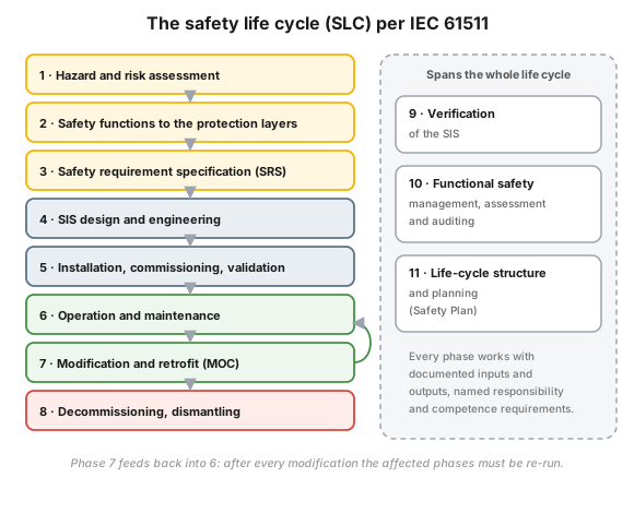 Figure 4 — the phases of the safety life cycle; LOPA and SIL are decided in phases 1–2, but phases 6–7 keep them alive.
The documented procedure of a LOPA study can be condensed like this:
- Select the scenario. From the HAZOP deviations we select the scenario to be examined. One LOPA applies at a time to a single scenario; suitably to one cause plus one consequence.
- Severity and tolerable frequency. We determine the severity of the consequence for people, for the economic impact and for the environment, and we assign the tolerable event frequency (TEF) to it.
- Initiating causes and modifying factors. We estimate the frequency of the initiating event (f), the probability of the enabling factors (P_E) and the consequence-modifying factors (P_C); from this the unmitigated event frequency (UEF) follows.
- The IPLs and their PFD. We identify the layers, assign a PFD to each, and add up the resulting risk reduction. From this comes the mitigated event frequency (MEF).
- Comparison and decision. We measure the MEF against the tolerable limit, and if needed we assign a SIF to it with the required SIL.
- Documentation, checking, approval.
The requirements go into the safety requirement specification (SRS): function, SIL, safe state, process safety time, test interval, operator interfaces. The SIL workshop should be cross-functional: operations, process safety, maintenance, process control and the process engineer together.
Hands-on / mini-scenario
Section titled “Hands-on / mini-scenario”Check one credited IPL tomorrow. Choose a scenario from the LOPA of your area, and walk through it:
- Does it physically exist? Find the layer in the field and on the P&ID; if it is a SIF: which loop, with what voting?
- Is it in service? Is there an active MOS/POS for it in the bypass register, since when, and when does it expire?
- Has it been tested? Does the last trip test fit within the test interval prescribed in the SRS? An overdue test = a lost SIL.
- Is it independent? Does the same transmitter serve the control and the alarm? Then the credit is invalid at one of the layers.
- Is there a person and time behind it? If the layer is an alarm: is there a written alarm response procedure, is the operator trained, and do at least 10 minutes remain?
Homework. Write down how many credited layers survived, and by how much the resulting frequency of the scenario has grown.
Measurement / audit (metrics, formulas where they exist)
Section titled “Measurement / audit (metrics, formulas where they exist)”The result of a LOPA is a number; the audit asks whether it is still true. The basic formulas:
- Resulting accident frequency:
f(MEF) = f(initiating event) × P_E × P_C × PFD₁ × PFD₂ × … × PFDₙwhere P_E is the probability of the enabling factors and P_C that of the consequence-modifying factors. The value without the layers is the UEF, the reduced one is the MEF; this is what we measure against the TEF. - Risk reduction factor:
RRF = 1 / PFD, for example with PFD = 0.01, RRF = 100, which is the lower limit of SIL 2. - Condition on the process safety time:
t(alarm response) + t(process dead time) ≤ PST. If this is not met, the alarm cannot be credited as a layer.
Audit and performance indicators to follow:
- Share of SIF trip tests carried out on time (%): the credited SIL is real only if the test interval is kept.
- Number and age of active MOS/POS bypasses: every bypassed SIF is a missing IPL.
- Performance of the safety-critical alarms: not suppressible, enough PST margin, regular bad-actor and stale alarm review.
- Audit of IPL integrity: do the credited layers exist, are they independent, tested, documented?
Common mistakes
Section titled “Common mistakes”- One sensor, two roles. The same measurement serves control and protection: a common failure mode arises, and the credit is false.
- Over-crediting the operator action. A value above RRF 10 is not permitted for the alarm plus human layer; in such a case a SIF is needed.
- Ignoring the PST. If the operator physically has no time to act, the alarm is not a layer, however “critical” its label is.
- Invisibly bypassed SIF. The LOPA is fine on paper, but because of the isolation the layer is not in service; without a register and a daily check the LOPA is fiction.
- Misunderstanding SIL as a property of equipment. A component certified as SIL 2 does not on its own give a SIL 2 function.
- Alarm or trip point modification without MOC. Shifting the limit without feeding it back into the HAZOP/LOPA invalidates them.
When NOT to use it (the limits of the method)
Section titled “When NOT to use it (the limits of the method)”LOPA is fast and strong, but it gives a correct result only if its assumptions hold:
| Situation | Why LOPA is not the answer | The right answer |
|---|---|---|
| The scenarios have not yet been uncovered | LOPA calculates on existing ones, it does not find new ones | HAZOP, HAZID, What-If |
| You would examine several scenarios at once | one LOPA is valid for a single scenario at a time | a separate LOPA per scenario |
| A common-cause or common-mode failure is possible between the layers | the multiplication assumes complete independence | fault tree analysis (FTA) |
| LOPA gives a SIL 3 result | the uncertainty of the semi-quantitative estimate is already too large here | quantitative procedure: extended LOPA, FTA or QRA |
| The calculation would demand a SIL 4 level solution | a solution at SIL 4 risk level is not acceptable | the risk has to be reduced at the source, distributed over several different layers |
Rule of thumb: LOPA answers the question of the sufficiency of the layers on an already known scenario. It does not replace hazard identification, and it does not carry a very large risk reduction requirement.
Take it home (keys)
Section titled “Take it home (keys)”- LOPA is a multiplication, SIL is the filling of the gap: first count the layers, only then design a SIF.
- Credit is given only for the four requirements: independent, specific, dependable (quantifiable), auditable.
- An alarm plus a human is at most RRF 10, at least 10 minutes. If the PST is less than this, the layer does not exist.
- SIL belongs to the function, not to the device: the whole loop has to be sized and kept tested.
- At SIL 3 switch methods, do not design a SIL 4: SIL 3 requires quantitative checking, a SIL 4 solution is not acceptable.
- The subject of the audit is not the document but the layer: bypass register, date of the trip test, sensor independence.
Self-test
Section titled “Self-test”- In a scenario the frequency of the initiating event is 0.1/yr, and two IPLs protect: an independent BPCS instrumentation and a 1oo1 SIF. What is the resulting frequency, and which risk band does it fall into?
- The sensor of a critical alarm is the same transmitter that also serves the control. Can it get IPL credit, and why?
- What is to be done if LOPA gives a SIL 3 result, and what if it gives SIL 4?
How does it appear in digital practice?
Section titled “How does it appear in digital practice?”The result of LOPA and SIL is a static document, but the status of the credited layers changes shift by shift. The digital mapping therefore does not replace the analysis; it makes the live status of the layers visible.
| LOPA/SIL principle | Digital implementation | What it delivers |
|---|---|---|
| An IPL is worth something only in service | interlock and override log with a time stamp, list of open bypasses | it is visible which credited layer is missing right now |
| The SIL depends on keeping the test interval | trip test scheduler, due-date alert, trail of the test result | an overdue test does not go unnoticed |
| A credited alarm comes with an intervention | recording of the critical alarm and the response given to it | it is demonstrable that the layer worked |
| Every interlock and alarm point change is subject to MOC | approval workflow with feedback into the HAZOP/LOPA | the analysis does not become obsolete unnoticed |
| The credit demands auditability | versioned HAZOP/LOPA register, per scenario | the audit trail can be reconstructed |
Connection to OPEREX (shift log)
Section titled “Connection to OPEREX (shift log)”The OPEREX shift log makes the actual availability of the layers auditable: it records item by item the switching on and off of the MOS/POS bypasses, the critical alarms and the operator action given to them, as well as the fact of the trip test and the ESD check, shift by shift. This way HSE and the shift management can prove the real status of the assumed IPLs.
Terminology (HU / EN)
Section titled “Terminology (HU / EN)”| Hungarian | English / abbreviation |
|---|---|
| Védelmi réteg elemzés | Layers of Protection Analysis — LOPA |
| Független védelmi réteg | Independent Protection Layer — IPL |
| Biztonsági integritási szint | Safety Integrity Level — SIL |
| Műszerezett biztonsági funkció | Safety Instrumented Function — SIF |
| Műszerezett biztonsági rendszer | Safety Instrumented System — SIS |
| Igénykori hibavalószínűség | Probability of Failure on Demand — PFD |
| Kockázatcsökkentési faktor | Risk Reduction Factor — RRF |
| Kiváltó esemény | Initiating event |
| Tűrhető eseménygyakoriság | Tolerable Event Frequency — TEF |
| Mérsékelt eseménygyakoriság | Mitigated Event Frequency — MEF |
| Folyamatbiztonsági idő | Process Safety Time — PST |
| Biztonsági életciklus | Safety Life Cycle — SLC |
| Biztonsági követelmény-specifikáció | Safety Requirement Specification — SRS |
| Alap folyamatirányító rendszer | Basic Process Control System — BPCS |
| Vészleállító rendszer | Emergency Shut Down — ESD |
| Felülbíráló (kiszakaszoló) kapcsoló | MOS / POS override switch |
What is the relation between LOPA and SIL, which comes first?
LOPA comes first. For the hazard scenarios of the HAZOP it counts the existing independent layers, and calculates whether the risk reduction is enough. If it is not enough, SIL determination says with what SIF the gap has to be filled: SIL is the answer to the gap signalled by LOPA.
Does a critical alarm plus operator action count as a SIF?
No. An alarm plus a human can be a protection layer, but it is worth at most an RRF 10 credit, and only with an intervention of at least 10 minutes, within the process safety time. A SIF gives greater integrity than this, automatically, designed in accordance with IEC 61508/61511.
What does SIL 2 mean numerically?
On demand the SIF fails with a probability of at most 1% (PFD 10⁻²…10⁻³), that is, it guarantees a risk reduction of 100–1000-fold, provided that it is maintained and tested with the prescribed test interval.
Why does a "good" LOPA fail in practice?
Because the real availability of the credited IPLs is not ensured: a bypassed SIF, an overdue trip test, a shared sensor, or an alarm limit shifted without an MOC.
Should one aim for SIL 4 for maximum safety?
No. A protective solution at SIL 4 risk level is not acceptable. If the calculation leads here, the risk has to be reduced at the source, and distributed over several mutually independent layers working on different principles.
Related concepts
Section titled “Related concepts”HAZOP | management of change | ESD systems | alarm management | operational risk assessment | IOW and the technological card | FMEA | near-miss
Next step
Section titled “Next step”If you have understood this, from here it is worth going on, in this order:
- HAZOP — the hazard identification that gives the input of the LOPA.
- ESD systems — the operational embodiment of the SIS: C&E chart, trip logic, bypass handling.
- alarm management — maintaining the credited alarm layer: rationalization, PST margin, bad-actor review.
References / further reading
Section titled “References / further reading”- IEC 61508 (MSZ EN 61508) — the basic standard of functional safety.
- IEC 61511 (MSZ EN 61511) — functional safety in the process industry: the source of the safety life cycle and the SIS requirements.
- IEC 61511-3, Annex F — the four requirements of the protection layers and the application of LOPA.
- ANSI/ISA-84.01 (ISA, 1996) — the first SIS standard, the American predecessor of IEC 61508.
- CCPS (AIChE): Layer of Protection Analysis: Simplified Process Risk Assessment — the handbook of LOPA.
- Seveso III Directive: 2012/18/EU on the control of major-accident hazards involving dangerous substances.
- Eduardo Calixto: Gas and Oil Reliability Engineering. Gulf Professional Publishing, 2016.