Storage and movement in a tank farm
≈ 29 min read · 5,880 words
The level of one tank is slowly rising while the operator believes they are pumping into another. A badly built route (line-up) leads within minutes to an overfill, cross-contamination or an off-spec batch. A tank farm is not a passive warehouse but an actively operated unit: this is where feedstock receipt, intermediate storage, blending and finished-product dispatch all come together. This article walks through the operating logic of storage and product movement.
Storage and product movement means holding feedstock, intermediates and finished product in tanks and moving them on a controlled route (line-up).
It covers receiving, transfer between tanks, blending and the dispatch of finished product by loading and unloading or by pipeline. The key is the controlled route, accurate inventory records and independent protection against overfill.
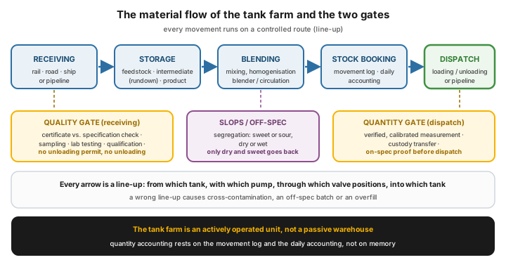 The material flow of the tank farm: a quality gate stands on the receiving side, a quantity gate on the dispatch side, and every arrow is a controlled route.
Who is this for?
Section titled “Who is this for?”This article is for those whose work touches the daily running of the tank farm: operator and shift supervisor · plant manager · production planner · logistics and dispatch specialist · quality inspector · process safety specialist · reliability engineer.
Learning objectives
Section titled “Learning objectives”After reading this article you will be able to:
- name the tank types by design and by roof structure, and their role in the tank farm (feedstock, intermediate, product, slops);
- describe what controlled route building (line-up) means, why it is critical, and why a double check is weak on its own;
- explain the logic of inventory records and quantitative handover (custody transfer), including dry oil basis accounting;
- list the types of storage loss (breathing and working loss, water draining, leakage, cleaning) and the means of reducing them;
- list the design rules of overfill protection, and apply the barrier independence test;
- place the tank farm in the plant’s cross-functional web of relationships (quality, logistics, safety).
The essence
Section titled “The essence”- The tank farm is an actively operated unit, not a passive warehouse: receiving, intermediate storage, blending, dispatch.
- The line-up (route building) is the most critical operation: a wrong valve position leads to overfill or cross-contamination.
- Inventory is kept in physical units; the measurement is the basis of production accounting and of custody transfer, and it closes on a dry oil basis.
- Overfill protection primarily interrupts the filling automatically; where it only signals, the time margin of the pre-alarm is the design condition.
- The roof design decides the evaporation loss: against the large vapour space of a fixed roof tank, the floating roof and the rim seal give the protection.
- Before dispatch the product’s on-spec status must be proven (see product quality); on the receiving side the unloading permit is the gate.
Why it matters (the stakes)
Section titled “Why it matters (the stakes)”The tank farm is the buffer and handover point between the plant and the market: this is where it becomes visible how accurate the material balance is and how disciplined the operation is. After flaring, storage loss can account for the largest part of plant hydrocarbon loss if no steps are taken to reduce physical loss and to establish good measurement practice; and the main cause of the month-to-month swing in loss is the inaccuracy of inventory and storage data. Overfill is one of the most severe process-industry accident scenarios: the escaping, evaporating hydrocarbon can form an explosive vapour cloud. Cross-contamination from one wrong route can turn a whole tank of product off-spec. Tank farm operation therefore carries a direct safety, quality and economic stake.
What does the tank farm store, and how does material move?
Section titled “What does the tank farm store, and how does material move?”The tanks of a tank farm differ by function:
| Tank type | Role |
|---|---|
| Feedstock tank | receiving and buffering the incoming raw material |
| Intermediate (rundown) tank | storing intermediate material between units |
| Product tank | storing finished product until dispatch, often with blending |
| Slops / off-spec tank | material outside specification or recycled back |
The path of the material is typically: receiving → intermediate storage → blending → booking to stock → dispatch. Every movement happens on a controlled route (line-up): with the deliberate, checked build-up of the pump, the valve set and the destination tank.
What tank types are there by design?
Section titled “What tank types are there by design?”Beyond function, the classification by design decides what may be put into the tank and how large its evaporation loss will be. Storage is atmospheric when the tank’s internal space is in direct (breathing) contact with the surroundings, or, in a closed system, when the overpressure in the vapour space does not exceed 70 mbar and the vacuum 20 mbar for a horizontal cylindrical tank, and the overpressure 55 mbar and the vacuum 10 mbar for a vertical cylindrical tank.
The main classification axes:
- Horizontal or vertical cylindrical. For storing large quantities, the vertical cylindrical design has become widespread.
- Underground or above ground. A tank also counts as underground if its top generatrix lies at least 0.3 m below ground level, as does the earth-covered design.
- Single wall, guard ring, double wall, double bottom. A tank has a guard ring if it has a steel outer containment jacket; it is single wall if an earth embankment or a concrete dike surrounds it. In a double wall tank the tightness of the space between the two jackets can be checked.
- By roof design (with the greatest operating consequence): fixed roof, external floating roof, internal floating roof.
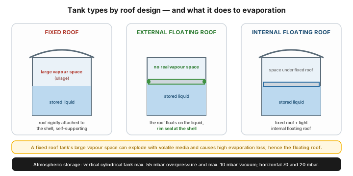 The three roof design types. The fixed roof works structurally together with the shell, the floating roof floats on the liquid, and the internal floating roof design combines the two.
The roof of a fixed roof tank is rigidly connected to the shell, so a large vapour space remains. With a volatile medium this can readily explode, and it causes a high evaporation loss. An external floating roof tank has practically no vapour space: the roof floats on the stored liquid, and evaporation is reduced to a minimum by the rim seal between the shell and the floating roof. The internal floating roof design places a light floating roof under a fixed roof. A floating roof tank is more expensive (a more complex structure, rainwater drainage, stricter manufacturing and inspection requirements), but the substantially lower evaporation loss pays it back quickly, and its environmental load is lower too.
Why a floating roof, and what does the rim seal do?
Section titled “Why a floating roof, and what does the rim seal do?”The rim seal is the mechanical element of the tank that reduces or prevents the evaporation and splashing of the stored liquid, and on an external floating roof tank the ingress of rainwater as well. The seals must be designed to withstand the friction on the tank wall and the effects of the contents, to tolerate the manufacturing tolerances of the shell and the floating roof, the lateral movement of the floating roof and the deformation caused by the weather.
The rim seal has two layers:
- Primary seal — the layer of endless elements partly immersed in the liquid, which elastically evens out the irregularities of the tank wall. It can be made of spark-free metal (long life, less sensitive to damage, but more costly) or with a flexible, foam-filled construction (good sealing ability, cheaper, but more vulnerable, and when damaged the foam can become saturated with the stored medium).
- Secondary seal — outside the stored liquid, above the primary seal. Its accessory can be a flexible stainless steel plate providing the equipotential bond, which keeps sliding contact with the shell.
Evaporation does not stop at the shell: the guide poles and gauge poles led through the floating roof, and the roof legs, must be sealed too. After the seal ring the gauge pole is the next biggest source of loss, which is why it gets a cover or a sleeve. Do not take a sample from an unperforated gauge pole: its contents are not representative of the tank’s mass.
Where is hydrocarbon lost in storage?
Section titled “Where is hydrocarbon lost in storage?”Storage physical loss has four sources: evaporation, hydrocarbon-bearing water draining, leakage, and tank cleaning and waste handling. Within these, evaporation loss has two basic types:
- Breathing loss — the vapour leaving a standing tank, typically because of the expansion and contraction caused by the daily temperature swing.
- Working loss — the loss arising from the level change caused by filling and emptying: on filling, the liquid pumped in displaces the vapour space; on emptying, the product evaporates from the wetted shell surface that becomes exposed.
In a fixed roof tank the breathing loss is relatively small next to the working loss, so it is misleading to talk about breathing loss only.
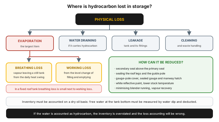 The taxonomy of storage loss and the means of reduction. Inventory closes on a dry oil basis: the free water at the tank bottom must be deducted.
How can it be reduced? With a secondary seal above the primary one, with the sealing of the floating roof legs and the guide pole, with a gauge-pole cover and sealed gauge and manway hatches, with white, reflective paint, a lower stock temperature, minimising the running of the blender, and with a vapour recovery system. A product with a high vapour pressure may only be stored in a fixed roof tank if that tank is fitted with an internal floating roof or with a pressure relief system connected to a vapour recovery unit.
Water draining cuts both ways: it is necessary, because free water gathers at the tank bottom (from settling, from dissolved water separating out, or from rainwater ingress), but with manual draining it can cause a serious hydrocarbon loss if the operator leaves the valve open. Manual drain valves must therefore be marked unambiguously, so that they are not confused with the roof drain, and the drained, hydrocarbon-bearing liquid must be collected in a closed system.
What is the controlled route (line-up), and why is it critical?
Section titled “What is the controlled route (line-up), and why is it critical?”The line-up is the route building before the movement: from which tank, with which pump, through which valve positions, into which tank the material goes. A faulty line-up is the most frequent serious error in the tank farm:
- wrong destination tank → cross-contamination, off-spec batch;
- closed discharge side → pump or pipeline damage;
- route left open → unwanted flow-through, overfill.
That is why the line-up is treated as a checked step: a double check, confirmation of the valve positions, and watching the level and pressure trends during the movement (see the standard operator round).
If the check is nevertheless counted as a control, three conditions must be prescribed in writing: the check must take place on site (a manager’s signature on the work permit is not enough), the checker must identify the equipment by the field tag, and must satisfy themselves of its state objectively, without relying on prior knowledge or assumption.
How do you receive material?
Section titled “How do you receive material?”Receiving is not a single arrow on the diagram but a chain of steps, in which every step has an owner and a document. For rail or road arrivals the typical order is:
- Advance notice and mill certificate in advance; if missing, they must be requested.
- Comparing the certificate with the specification. A deviation from the contracted specification must be handled before the arrival.
- Taking over from the carrier, the handover of the transport documents, setting the receiving order.
- Checking the condition of the transport equipment, reporting with a record in case of a fault.
- Weighing (gross). A weight deviation above the threshold must be flagged, and the accounting data amended.
- Sampling according to the procedure in force, with sample retention where needed.
- Lab testing with the tests named in the specification, with calibrated, checked or verified measuring instruments, with the result recorded electronically.
- Qualification. If every result meets the specification, the material is of adequate quality; the decision must be recorded in writing.
- Unloading permit. In case of a failed qualification the laboratory may not issue an unloading or acceptance permit; a separate quality concession can then be requested, and until then the material may not be unloaded.
- Unloading, then receipt into the tank farm or into the plant, according to the technological instruction.
- Weighing (net) on the quantity actually received; on a larger deviation, a quantity claim.
- Keeping the movement log, daily accounting, and finally booking to stock.
For a pipeline arrival the chain is shorter, but the logic is the same: sampling and tank qualification on the sending side, a quality concession in case of non-conformity, then sampling on the receiving side, movement log, daily accounting and booking to stock.
The lesson: on the receiving side the quality gate is the unloading permit, on the dispatch side the quantity gate is the verified measurement. If either gate becomes a formality, the error lands in the tank farm.
How do you record inventory and handover?
Section titled “How do you record inventory and handover?”Tank farm inventory is kept in physical units (mass/volume), typically from level and temperature measurement, with a density correction. This data serves a twofold purpose:
- it is the basis of the daily material balance and of yield (see production accounting);
- it is the basis of the quantitative custody transfer at receipt and at dispatch, where the measurement has legal and commercial significance.
Four rules make the records reliable:
- Dry oil basis. The free water at the tank bottom must be measured with a water dip before the accounting period is closed, and deducted from the inventory. If the water is accounted as hydrocarbon, the inventory is overstated and the loss accounting will be wrong. For groups of tanks it is worth keeping a water balance as a control too.
- Tank calibration. A tank that is part of the accounting system must be calibrated regularly. Recalibration is needed after a significant modification or major overhaul, because of movement or settlement of the foundation, or if the density of the stored medium changes; in that case the change of the reference height must be handled as well.
- Automatic measurement, manual fallback. If the accuracy of the automatic level gauge or tank thermometer becomes suspect, an instrument technician must service it and prove the calibration, and until then manual tank gauging must be used for the accounting.
- Competence and audit. Whoever takes part in measurement or data recording should be trained for their task; the equipment, the calibration records and the measurement methods must be subjected to a periodic audit.
The inventory deviation (measured vs. book) is handled by reconciliation; a persistent deviation points to a measurement error, a leak or a gap in the records.
Slops need separate handling
Section titled “Slops need separate handling”The slop system collects off-spec and recovered oil from every area of the plant, typically for reprocessing in the crude distillation unit. Its sources include: the off-spec streams of start-up, shutdown and upsets, line flushes before sampling, oily sewer collection pits, oil recovered from the wastewater treatment plant and from tank water draining, and returned off-spec products.
The segregation of slops is a key element of designing and operating the system: the water-bearing sources must be separated by their sweet or sour character, so that in the end only relatively dry and sweet slop oil goes back into processing. Sources containing sour water go into a separate tank, where the phases separate: the water to the sour water stripper, the oil to the slop oil tank. Accurate slop inventory measurement directly affects the quality of the material balance: a bad measurement causes large loss and profit swings from month to month.
Loading and unloading
Section titled “Loading and unloading”Finished product is dispatched and raw material received by loading and unloading (rail car, road tanker, ship) or by pipeline. The loading rack is a separate operating and safety unit: identification before filling, earthing (against static build-up), overfill protection and vapour return (where it exists) are all fixed steps. The loading arms must be drained down into the ship, and preferably fitted with a pump-back system so that the residual material is not lost; every other drain-down must be collected and pumped back into the slop system.
Process-industry and safety context
Section titled “Process-industry and safety context”Storage is one of the focal points of the Seveso classification, because the large quantity of hydrocarbon stored in one place is a significant hazard source.
The design rules of overfill protection
Section titled “The design rules of overfill protection”An overfill protection device is a system assembled from elements that, in good time, on reaching the tank’s permitted filling level, interrupts the filling process. The mandatory elements of the design:
- It should primarily interrupt. The preferred solution is the automatically intervening system that stops the filling on reaching the permitted filling level.
- If it only signals, a pre-alarm is needed too. In that case a separate pre-alarm is required, and the position of the pre-alarm must be set so that enough time remains for manual intervention until the permitted filling level is reached. Manual intervention is therefore a legitimate final element, but only with this strict design condition.
- Fail-safe behaviour. On failure of the device it should interrupt the filling and/or trigger an audible alarm.
- Independent sensors. For the overfill signal and for the pre-alarm, sensors independent of each other must be used.
- Separation from the level measurement. The overfill signal and the level measurement must be solved with independent, separate devices. In the level gauge, sensors containing no moving parts should be preferred.
The barrier independence test
Section titled “The barrier independence test”The principle behind the design rules is that protection layers must be effective, independent and auditable. Independence means that if a single fault can knock out more than one control, then those controls in reality amount to one single control.
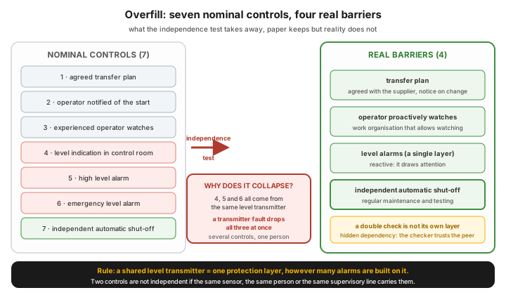 The seven nominal controls of a tank filling bow-tie collapse to four after the independence test.
A typical tank filling bow-tie names seven controls: an agreed transfer plan, notifying the local operator of the start, an experienced operator watching the filling, level indication in the control room, a high level alarm, an emergency level alarm, and finally an independent automatic shut-off. After the test is carried out, four remain, because the level indication and both alarms come from the same level transmitter: if the transmitter fails, all three fall at once. In the same way, several controls that rely on the same one person, or on the same direct supervisory line, are not independent either.
Two human controls can still be separated if one is proactive (the operator watches the filling even without an alarm) and the other reactive (the alarm draws the attention). These are not as strong as technical independence, but with careful design they remain meaningful layers. Every barrier has escalation factors too: an unexpected change of the plan (countermeasure: communication with the supplier), the operator not watching the transfer (understanding that the operation is safety-critical, and a work organisation that also allows the watching), and finally the failure of the level transmitter or of the independent shut-off (for both: regular, planned maintenance and testing).
Containment, fire protection, integrity
Section titled “Containment, fire protection, integrity”- Bunding. Every tank or tank group has an external containment area, made of non-combustible material (earth, concrete or steel). In sizing it, allowance must be made for liquid escaping as a jet on a puncture to end up in the containment area too; a concrete channel around the tank foundation collects leakage from the fittings and the shell.
- Rainwater handling, an operator rule. The drain fittings of the containment areas are kept closed, and in a downpour or rainy weather they may only be opened if the operator has satisfied themselves that the outflowing water is not contaminated. In case of contamination, soil replacement must be carried out at an earth-basin containment area.
- Fire protection. Vertical cylindrical tanks may carry roof and shell cooling as well as foam extinguishing equipment; the purpose of the cooling is for the tank to keep its stability in case of fire.
- Mandatory fittings. Manway (dome), filling and suction pipe with a shut-off fitting, bottom draw-off, pressure-balancing breather valve or vent, earthing connection and lightning protection, gauge and sampling hatch, level gauge, and the structural elements of the overfill protection.
- Management of change. Changing the storage mode, the tank assignment or the route goes through management of change.
What fails on a tank?
Section titled “What fails on a tank?”A significant part of the failures occur because of corrosion or a weld defect, and the most dangerous consequence is leakage or a puncture. The recurring patterns:
| Failure | Mechanism | Countermeasure |
|---|---|---|
| Bottom plate and corner weld corrosion | the most frequent leak site; attacked from the medium and from the soil alike, water running down the shell acts as an electrolyte | drip ring, internal coating, cathodic protection, double bottom with check nozzles |
| Shell and fixed roof puncture | hard to detect on an insulated tank; water getting into the insulation is a corrosion hotbed | watching the run marks of the drip ring, excluding water ingress from the insulation |
| Breather valve failure on emptying | blockage, sticking or freezing creates a vacuum, and the thin-shelled tank is sucked in | maintenance of the breather valves and the flame arresters, heated design where freezing occurs |
| Internal explosion on filling | the roof plate is joined to the shell with a weakened weld, so that an explosion is vented upwards (frangible roof principle) | managing the vapour space, keeping to cleaning and hot work rules |
| Sinking of the floating roof | mechanical jamming on the shell or at the guide pole; puncture of the parts in contact with the liquid; gas getting under the roof tilts it | regular visual inspection, checking the pontoon inspection hatches and the rim seal |
| Total loss | a tank fire from a lightning strike, or an explosion caused by inadequate cleaning or hot work in breach of the rules | lightning protection, cleaning and work permit discipline, checking the fire protection equipment |
Prevention is the most effective tool: careful design and close condition monitoring. During normal operation most tank faults are hard to handle, and generally can only be repaired by fully emptying the tank.
Putting it into practice
Section titled “Putting it into practice”Tank farm discipline is not a big project but a few enforced steps. This is how you would introduce a line-up checklist starting tomorrow:
- Pick one operation where the stake is highest: typically the largest-volume, most frequent transfer, or the unloading of incoming material.
- Draw up the route as it really is (source tank → pump → valve set → destination tank), and name every fitting by its field tag identifier.
- Write the list in action-led steps, with the expected position for each step: “Open … Check that … is closed … Confirm it on the … indication.”
- Build in objective confirmation: not “I looked at it”, but “I confirm it on the basis of the tag identifier and the position indication”.
- Make watching the level and pressure trend mandatory during the movement, and name the deviation at which the job must be stopped.
- Record the start and the close with a timestamp in the log, together with the tank and route identifier.
- Review the first ten uses of the list with the shift, and fix whatever does not work in reality.
Workshop exercise (60 minutes, with the shift team). Take your own tank filling scenario and list every control you regard today as a protection. Then carry out the independence test: cross out the ones that depend on the same sensor or on the same one person. How many real barriers are left? If fewer than two, there is work to do right away.
Homework. During one shift pick three tanks and check: when they last had a water dip, when their level measurement was calibrated, and when their overfill protection was tested. If there is no data for any of them, take that gap into the shift handover.
Measurement and audit
Section titled “Measurement and audit”The tank farm carries two separate measurement regimes at once: that of quantitative accounting and that of mechanical integrity.
| What we measure or inspect | On what cycle | What it is good for |
|---|---|---|
| Full structural inspection with internal cleaning | every 10 years | review of every structural element of the tank; the cycle can be extended under conditions by 2 years for a single bottom and by 3 years for a double bottom |
| Tightness test | every 5 years | proof of leak-tightness; at revision over the full fillable height |
| Bottom wall thickness measurement (on the magnetic flux leakage principle) | at the time of the structural inspection | mapping the external and internal side wastage and local corrosion of the bottom plate |
| Tank calibration | regularly, and after modification, major overhaul, foundation settlement or a density change | the basis of custody transfer and of the inventory figure |
| Instrument audit | periodically | proof of the adequacy of the calibration records, the instruments and the measurement methods |
| Inventory reconciliation | per accounting period | measured vs. book deviation; a persistent deviation must be investigated |
In inspection, the greatest strength load on the tank falls on the weld at the meeting of the shell plate and the bottom plate, so the focus of condition checking is the lower part of the shell and the bottom plate.
Common mistakes
Section titled “Common mistakes”- A faulty line-up. A wrong valve position → cross-contamination or overfill. Instead: an on-site check proven by the tag identifier, objective position indication, trend watching; the double check is a supplement, not a standalone layer.
- Overfill protection depending on the operator. Instead: an automatically interrupting system; where there is only a signal, a pre-alarm with enough time margin, an independent sensor, and a device separate from the level measurement.
- Neglecting the inventory deviation. The persistent deviation is not investigated. Instead: regular reconciliation on a dry oil basis, with a water dip, with root cause analysis of the deviation.
- Off-spec mixing into the product. Slops or off-spec recycled without control. Instead: segregation of slops by sweet/sour and dry/wet, on-spec proof before dispatch.
- Evaporation as “a given”. Faults of the seals, the gauge pole and the leg seals are not repaired. Instead: regular rim seal checking and maintenance, secondary seal, gauge-pole cover, reflective paint.
- The breather valve gets no attention. A blocked or stuck breather sucks the tank in on emptying. Instead: bringing the breather valves and flame arresters into the maintenance and round routine.
When NOT to use it this way?
Section titled “When NOT to use it this way?”| Situation | Why | The right answer | |
|---|---|---|---|
| Custody transfer measurement | a legal and commercial stake | verified, calibrated measurement, not an operational estimate | |
| Suspect automatic level measurement | a faulty transmitter spoils the inventory and the alarms at once | fall back to manual tank gauging until the technician proves the calibration | |
| A change touching the design basis | the capability of the tank or route is limited | [[moc.en | management of change]], not a verbal decision |
| A safety-critical overfill scenario | consensus is not enough | HAZOP / LOPA on the protection layer; a double check cannot be counted as an independent layer | |
| A high vapour pressure product in a fixed roof tank | large vapour space, evaporation and explosion risk | internal floating roof or a pressure relief system connected to vapour recovery |
Take it home (keys)
Section titled “Take it home (keys)”- The tank farm is active operation, not a warehouse: the line-up is the primary risk, and a double check is not a barrier on its own.
- Overfill protection should primarily interrupt; if it only signals, the pre-alarm must leave enough time for manual intervention, with an independent sensor.
- Inventory is the common basis of the balance and of the handover, so reconciliation is not optional, and it must close on a dry oil basis.
- The roof design and the rim seal are an operating question: evaporation is not fate, it is maintainable.
- Before dispatch an on-spec proof is needed, at receipt an unloading permit; without a gate the error lands in the tank farm.
Self-test
Section titled “Self-test”- Why is the line-up the most critical operation of the tank farm, and why does a double check not count as a standalone protection layer?
- What is the difference between breathing loss and working loss, and which is the larger in a fixed roof tank?
- A tank filling bow-tie lists seven controls, but only four remain after the independence test. What is the most common reason?
How does this show up in digital practice?
Section titled “How does this show up in digital practice?”The principle of tank farm operation does not stop at the valve and the gauge tape: the same logic is realised in software too, in any well-organised production data environment. The mechanism differs, the principle is the same: disciplined movement and accurate accounting work when the data arises where and when the operation happens.
| Tank farm routine | Digital implementation | What it delivers |
|---|---|---|
| Building the line-up | digital checklist with a forced sequence, with the field scanning of the fitting’s tag identifier | the check is bound to the specific equipment, not to memory |
| Level and temperature tracking | automatic tank level and temperature collection, trend and deviation alarm | an unexpected level change of a standing tank surfaces by itself |
| Transfer and movement log | structured e-log with a timestamp, tank and route identifier | the daily accounting is built from raw data, not from later reconstruction |
| Water dip | recording the measured free water and deducting it automatically from the inventory | the inventory closes on a dry oil basis |
| Instrument status | a register of calibration dates, with an expiry warning | the custody transfer measurement stays auditable |
| Overfill protection test | scheduled function test, logging of the test result | the independent shut-off is provably working |
| Quality gate | the unloading permit recorded in the system, unloading can only be started with a permit | the gate is not a formality but an enforced step |
Connection to OPEREX (shift log)
Section titled “Connection to OPEREX (shift log)”The operating trail of the tank farm today typically lives scattered in three places: in a paper movement log, in the control room trends, and in the shift supervisor’s head. The OPEREX shift log collects exactly the layer from which the daily accounting and the reconciliation are built: the start and close of transfers with a timestamp, the line-up steps with the fitting identifiers, the tank levels and the water dip values, the unloading permits and the anomalies. This way the movement log is not an end-of-shift rewrite but a live, searchable trail, and the investigation of an inventory deviation starts from data, not from memory.
Terminology (HU / EN)
Section titled “Terminology (HU / EN)”| Hungarian | English |
|---|---|
| Tankpark | Tank farm |
| Útvonal-kiépítés | Line-up |
| Átadás-átvétel (mennyiségi) | Custody transfer |
| Túltöltés-védelem | Overfill protection |
| Légzési veszteség | Breathing loss |
| Munkaveszteség | Working loss |
| Merevtetős tartály | Fixed roof tank |
| Külső úszótetős tartály | External floating roof tank |
| Belső úszótetős tartály | Internal floating roof tank |
| Zárszerkezet (primer / szekunder tömítés) | Roof seal (primary / secondary seal) |
| Felfogó tér | Bund / bunding |
| Tartályfenéki víz mérése | Water dip |
| Száraz-olaj alapú elszámolás | Dry oil basis accounting |
| Tartály-hitelesítés | Tank calibration |
| Slop / off-spec anyag | Slops |
| Töltés-lefejtés | Loading / unloading |
| Készlet | Inventory |
Is storage an operating or a technology matter?
The daily running of the tank farm is operation (the shift handles the line-up, the levels, the dispatch). The quality of the stored material and the yield belong to technology (see product quality, production accounting).
Why is overfill protection a separate protection layer?
Because overfill is a severe, quickly escalating accident scenario. The protective device primarily interrupts the filling on reaching the permitted filling level; if it only gives a signal, a separate pre-alarm is needed, with enough time margin for manual intervention, with sensors independent of each other, and with a device separate from the level measurement.
Why is a double check not enough at the valve line-up?
Because its intended independence often does not materialise: the checker is inclined to believe that the experienced colleague did it right, and visual inspection does confirm that a valve is closed, but not that it is the correct one. That is why an engineered barrier is needed alongside it, and it cannot be counted as an independent layer in LOPA.
What is the difference between breathing loss and working loss?
Breathing loss is the vapour leaving a standing tank, typically because of the daily temperature swing. Working loss arises from the level change caused by filling and emptying. In a fixed roof tank the breathing loss is relatively small next to the working loss, so the two must be handled together.
Why must the water at the tank bottom be deducted from the inventory?
Because the accounting must be kept on a dry oil basis. If free water is accounted as hydrocarbon, the inventory is overstated and the loss accounting will be wrong. That is why a water dip must be taken before the accounting period is closed, on every tank where water accumulation is expected.
How often must a tank be inspected?
Under the relevant Hungarian regulation, the full structural inspection with internal cleaning is due every 10 years, the tightness test every 5 years. Where defined conditions are met, the internal cleaning and structural inspection cycle can be extended by 2 years for a single bottom tank and by 3 years for a double bottom one.
Related concepts
Section titled “Related concepts”the standard operator round | shift handover | operational risk assessment | emergency shutdown (ESD) | plant housekeeping | production accounting | product quality and spec management | management of change | HAZOP | LOPA and SIL
Next step
Section titled “Next step”- operational risk assessment — first put into a system how you identify and rank the operating risks of the tank farm.
- LOPA and SIL — then look at how a protection layer can (and cannot) be counted as independent in the overfill scenario.
- production accounting — finally, link the inventory figure to the material balance, so that the storage loss becomes visible in numbers too.
References / further reading
Section titled “References / further reading”- Energy Institute HM 31 — Guide to hydrocarbon management in petroleum refinery operations: the canonical guide to the taxonomy of storage loss, dry oil basis accounting, tank calibration and slop handling.
- API MPMS 19.1 and 19.2 — the estimation methods for evaporation loss (breathing and working loss) for fixed roof and floating roof tanks respectively.
- ISO 7507 (tank calibration), ISO 4266 (automatic level and temperature measurement), ISO 4512 (manual level measurement), ISO 4268 (temperature measurement) — the standards of the measurement regime.
- API 2350 — the industry standard for overfill prevention on storage tanks.
- API 650 / 653 — the design, and the inspection and integrity, of atmospheric storage tanks.
- 11/1994. (III.25.) IKM decree (Hungary) — on storage tanks for flammable liquids and melts; the national frame for the periodic inspection cycles and the licensing procedures.
- 9/2008. (II.22.) ÖTM decree (Hungary) — the sizing, structural design, safety systems and fire protection of storage tanks.
- Seveso III Directive (2012/18/EU) — the safety management requirements for major accident hazard establishments, storage among them.
- Process Safety Leadership Group (UK): Safety and environmental standards for fuel storage sites — a detailed treatment of barrier independence and the limits of the double check in a fuel storage context.